Istilah Jaringan Komputer
Pernahkah anda mendengar istilah Networking,network,workstation,server,client,dan stand alone komputer?
Computer Network :
Di dalam ilmu komputer, akan disebut Computer Network apabila ada beberapa komputer yang salingberhubungan satu sama lain dan dapat menggunakan perangkat lain secara bersama. Kelompok ini akan didaftar kedalam group yang sama. Kondisi seperti inilah yang disebut Computer Network.
Networking :
Pengertian networking adalah apabila ada beberapa komputer yang terhubung dalam jaringan yang sama dan saling berbagi akses, baik data maupun sumber daya peralatan. Networking juga sitem jaringan.
Workstation:
Dalam sebuah system jaringantidak hanya terdiri dari satu komputer.Berdasarkan pengertian tersebut, jaringan atau system jaringan adalah sekumpulan komputer yang terhubung satu sama lainyang membentuk satu group. Dari sebuah jaringan tadi, ada beberapa komputer yang tersambung, masing-masing komputer tadi disebut workstation.
Stand alone
Istilah stand alone merupakan kebalikan dari jaringan. Apabila komputer tidak tersambung dalam sebuah jaringan, komputer tersebut akan berdiri sendiri. komputer tersebut hanya bisa menggunakan sumber daya data peralatan lain yang ada dalam komputer itu sendiri. Inilah yang disebut stand alone.
Tentang Server
Server
Secara harfiah, server merupakan komputer yang berfungsi untuk mengatur atau menjadi koordinator dalam suatu jaringan komputer. Intinya, server merupakan induk dari semua komputer yang terhubung dalam suatu jaringan komputer. Server bertugas menangani penyimpanan, pengolahan, pendistribusian data secara terpusat, juga berfungsi sebagai pusat aplikasi bersama, serta pintu gerbang utama menuju internet (getway)
Contoh kerja server : Pada sebuah kantor yang terdapat 10 unit PC yang terhubung ke sebuah switch denga n kabel LAN. Ketika kita mengakses internet dari salah satu PC tersebut, sebenarnya PC tersebut tidak terkoneksi secara langsung ke internet, tapi dihubungkan oleh sebuah komputer induk yang disebut server. Disini server berfungsi sebagai Getway.
Contoh lain kerja server : pada sebuah perusahaan umum, biasanya digunakan aplikasi enterprise resource planning (ERP). ERP dijalankan oleh beberapa komputer,laptop,atau desktop di banyak divisi yang berbeda, yang jumlahnya bisa mencapai ratusan. Untuk mengelola sumber daya ini,diperlukan komputer induk untuk mendistribusikan informasi ke semua pihak yang membutuhkan.
3 hal yang perlu diwaspadai
TIGA HAL YANG HARUS DIWASPADAI
Diriwayatkan dari Rasulullah Sallallahu Alaihi wa Sallam bahwa beliau pernah
bersabda :
“Barangsiapa di pagi hari mengeluhkan kesulitan hidupnya (kepada orang
lain), berarti seakan-akan dia mengeluhkan Rabb-nya.
Barangsiapa di pagi hari bersedih karena urusan duniawi-nya, berarti sungguh
di pagi itu dia tidak puas dengan ketetapan Allah.
Barangsiapa menghormati seseorang karena kekayaannya, sungguh telah
lenyaplah duapertiga agamnya”.
Melakukan syikayah (pengaduan) atas nasib buruk yang dialami seseorang
kepada orang lain termasuk pertanda tidak ridha atas bagian yang telah
diberikan Allah. Kita tidak boleh melakukan syikayah, kecuali kepada Allah,
sebab syikayah kepada Allah termasuk bentuk do’a.
Hal ini sebagaimana disebutkan dalam riwayat dari Abdullah bin Mas’ud
Radhiyallahu Anhu bahwa Rasulullah Sallallahu Alaihi wa Sallam bersabda:
“Maukah aku ajarkan kepada kalian beberapa kalimat yang diucapkan oleh nabi
Musa ketika menyeberangi laut bersama Bani Israil?” Kami (para
shahabat) menjawab: “Tentu saja mau, ya Rasulullah. “Beliau bersabda:
“Bacalah: Alloohumma lakal hamdu wa ilaikal musytakaa, wa antal musta’aan,
wa laa haula wa laa quwwata illa billaahil ‘Aliyyil ‘azhiim.'”(Ya Allah,
segala puji hanya bagi-Mu, hanya kepada-Mulah kami mengadu. Tiada daya
(untuk menjauhi maksiat) dan tiada kekuatan (untuk taat), kecuali dengan
pertolongan Allah Yang Maha Tinggi lagi Maha Agung.)
Al-A’masy juga berkata: “Aku pernah bermipi didatangi seseorang. Dia
berkata: “Wahai Sulaiman, tambahkanlah pada do’a tersebut kalimat ini:
Dan kami memohon pertolongan kepada-Mu atas segala kesulitan yang ada pada
kami dan kami memohon kepada-Mu untu diberi kebaikan dalam segala urusan
kami.”
Oleh yang dipagi hari bersedih karena urusan duniawi dikatakan telah
membenci Rabb-nya, sebab hal itu mencerminkan bahwa dia tidak ridha dengan
qadha’ Allah, tidak bersabar atas cobaan-Nya, dan tidak beriman dengan
qadar-Nya, padahal semua yang terjadi di dunia ini adalah atas qadha’ dan
qadhar Allah.
Seseorang dilarang memuliakan orang lain karena hartanya, sebab menurut
syariat, seseorang hanya boleh memuliakan orang lain karena keshalihan dan
keilmuannya. Orang yang memuliakan harta di atas segala-galanya berarti
telah menghinakan ilmu dan keshalihan.
Syekh ‘Abdul Qadir Jailani qoddasallohu sirrohu (semoga Allah mensucikan
rahasianya) dalam pesannya telah mengatakan; “Setiap mukmin tidak boleh
lepas dari tiga hal berikut :
Melaksanakan perintah Allah;
Menjauhi larangan Allah;
Menerima qadha’ dan qodar.
—————————————————————————-
—————————
Sumber : Terjemahan Kitab Nashailul Ibad – Menjadi Santun dan Bijak
contoh head end tv kabel
berikut adalah contoh gambar diagram blok Head End TV Kabel
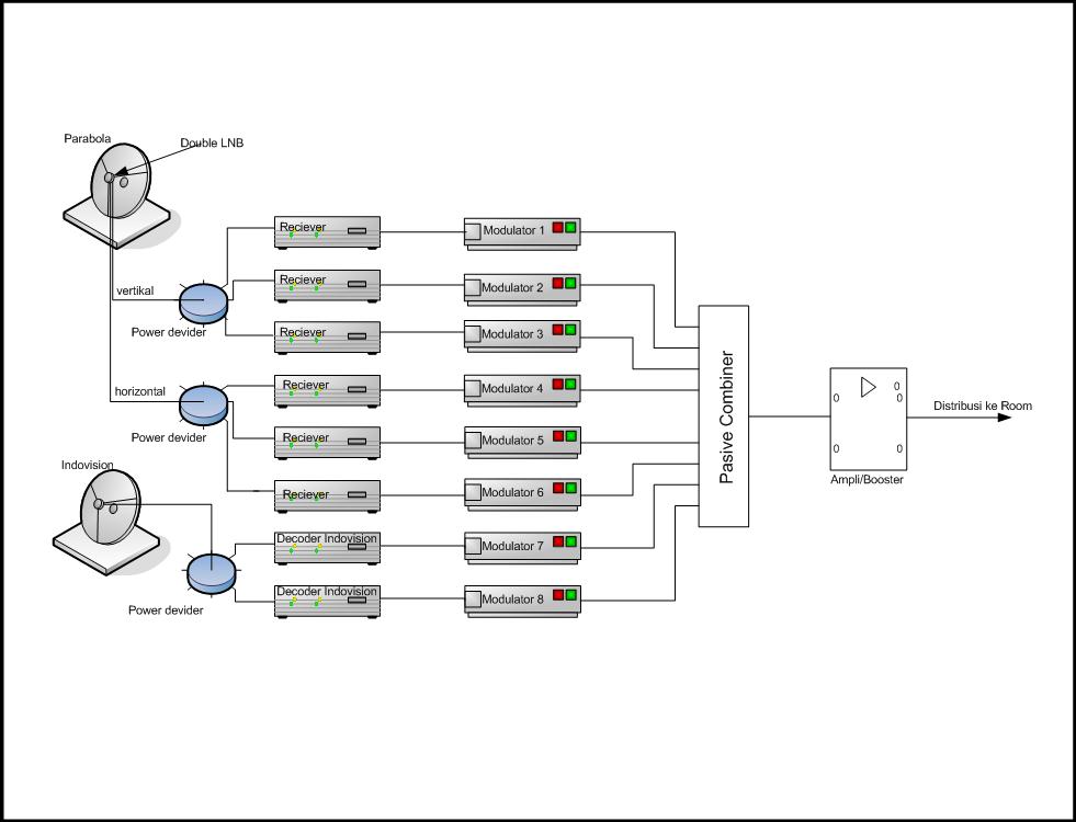


selengkapnya dapat dilihat di : http://www.masterantena.blogspot.com
")
berbagi ilmu dari forum sebelah
Mengatasi kerusakan TV sharp
oleh : nuketea
Pengarang : Http://coretanaba.blogspot.com
Diterbitkan di: Februari 12, 2009
Ciri TV sharp dalam kondisi protek adalah sebagai berikut: jika tv di hidupkan led indikator berwarna merah kemudian hijau terus beberapa detik kemudian berwarna merah lagi.
Untuk memperbaiki kerusakan TV Sharp dengan kondisi seperti ini (protec), bang Zic ( http://zicelectronic.blogspot.com) memberikan solusinya sebagai berikut:
Pertama anda harus bersihkan dulu mainboardnya dengan sikat atau kuas yg dipotong sekitar 2cm,untuk melihat dan memastikan adanya titik solder yg tidak baik,karena titik solder yg kendur akan tergerak dan dapat anda lihat dengan jelas.Gunakan cairan thinner high gloss ( berkualitas bagus dan cepat kering ) untuk membersihkan kotor atau noda pada mainboard.Setelah bersih,periksa semua titik solder di bagian : Vertikal-Regulator/power supply-Flyback.blok ini adalah yang paling sering terjadi kerusakan titik solder karena panas yang ditimbulkannya.terutama periksa solderan pada bagian kaki IC vertikal dan resistornya.
Ganti IC vertikal jika memang anda yakin rusak atau juga di tandai dengan berubahnya warna resistor vertikal.kerjakan dengan teliti.
Coba nyalakan pesawat TV dan perhatikan,jika masih tidak mau start secara normal ,ikuti langkah berikut ini:
Jika nyala led berwarna merah ke hijau dan berhenti menjadi kuning,kerusakan terjadi pada IC memory (24c04-24c16),ganti dengan yg baru.Setting kembali parameter di dalam servis menu. Jika led berwarna merah terus mati,kerusakan terjadi pada IC utama ( TDA 938psxxx ) atau kehilangan tegangan 3.3volt pada regulator,cek bagian power supply.
Jika berwarna hijau atau merah berkedip-kedip,ada kesalahan dalam IC memory.
ika led berwarna hijau selama 5-10 detik dan kembali merah,ada kegagalan pada bagian horisontal,periksa flyback ( cabut dan ukur dengan multimeter skala 10k pada kaki ground dan kaki yg menuju kolektor TR.output horisontal,jika bergerak meskipun sedikit berarti flyback sudah short.Juga periksa tegangan 180V untuk blok RGB,biasa terjadi kerusakan pada resistor pembatasnya .
Kesimpulan :
TV SHARP yang menggunakan IC utama seri TDA 938PSxxx,umumnya dan sering terjadi kerusakan pada : SOLDERAN YANG KURANG BAGUS, IC VERTIKAL, IC MEMORY,FLYBACK dan REGULATOR.
Tips ini sudah saya praktekan di rumah pada Sharp TV 14″ Universe dan berhasil dengan sukses. Tambahan untuk TV Sharp model ini jika gambar vertikal tidak normal (blank atas dan bawah sekitar 10 cm)coba short pin 6 dan 7 IC Utama (mode service) dan setting ulang vertikalnya ujar bang zic.
Bagi yang awam yang ingin mencoba di rumah Hati-hati ke setrum! ingat di TV masih ada setrum sisa (1-5 Kv) walupun colokan listrik TV sudah di lepas..
Menu servis TV
Sekarang hampir semua merk tv menggunakan media remote control untuk mengakses menu servis,baik untuk menyetel ukuran gambar,mengkalibrasi IF ataupun RGB,ataupun untuk menyetting suara dan yang lainnya.Namun untuk setiap merk TV menggunakan kode-kode yang berbeda untuk membuka menu-menu tersebut.
seperti salah satu contoh untuk membuka kode TV polytron yaitu:
1.Dalam keadaan standby,tekan menu di remote beberapa detik sampai televisi menyala dan meminta kode akses
2.tekan kode 1013 atau 1014 untuk dapat membuka menu-menu service yang tersedia
3.Gunakan tombol CH UP dan CH DOWN di remote untuk mengganti kriteria atau gunakan tombol VOL UP atau VOL DOWN di remote untuk mengurangi atau menambah kan.
Kode servis TV AKIRA:
1.Pada saat TV menyala,tekan tombol AV di remote
2.Lalu tekan tombol Menu,Qview dan mute maka akan keluar menu-menu servis di layar.
3.Gunakan tombol Timer untuk mengganti menu dan tombol VOL UP dan Vol DOWN untuk menambah dan mengurangi.
TOSHIBA : TEKAN MUTE DI REMOTE SEKALI,KEMUDIAN TEKAN LAGI DAN TAHAN MUTE + MENU DI TV .ULANGI UNTUK PROSES BERIKUTNYA
TEKAN MENU DIREMOTE-TEKAN ANGKA 4,7,2,5
TEKAN VOL(-) DI TV -TEKAN DAN TAHAN ANGKA 9
SANYO : MENU DI REMOTE + VOLUME UP TV
LG FLATRON: TEKAN OK DIREMOTE + OK DI TV atau MENU REMOTE + MENU DI TV
TCL : TEKAN DISPLAY (OSD) DIREMOTE + VOLUME DOWN DI TV ,tahan 3 detik
POLYTRON : POSISI TV STNDBY, TEKAN DAN TAHAN MENU DI REMOTE HINGGA TV MENYALA MASUKAN KODE ANGKA 1013.
PANASONIC : SHORT (KONEK SESAAT) PIN ‘FA-1’ KE ‘FA-2’ ATAU TP-8 KE GROUND
PANASONIC TX SERIES :TEKAN VOL(-) DI TV + OSD
SHARP : SHORT KAKI (PIN)6 DAN PIN 7 SESAAT PADA IC MCU (TDA 98XXX).UNTUK KELUAR SHORTKAN KEMBALI
SHARP EXPRESSION : HUBUNGKAN ATAU JEPIT DUA KAWAT /JUMPER J800 ( ADA DISEBELAH TUNER ) YG PCB- TELAH DISEDIAKAN LUBANG DAN DUA JUMPER SEJAJAR.
CRYSTAL : POSISI TV STNDBY,TEKAN VOLUME UP + VOLIME DOWN PADA TV BERSAMAAN DAN TAHAN HINGA TV ON
PHILLIPS : POSISI TV STNDBY,TEKAN 0,6,2,5,9,MENU
AKARI: TEKAN SLEEP DI REMOTE + MENU TV
SAMSUNG : POSISI STANDBY TEKAN DI REMOTE : MENU – PSTD – MUTE – POWER ON
SAMSUNG PLANO : POSISI STANDBY, TEKAN DI REMOTE : DISPLAY-MENU-MUTE-POWER ON
SAMSUNG PLANO DIGITAL HD100: STANDBY-DISPLAY-MENU-MUTE-POWER
ATAU : STANDBY-MUTE-1-8-2-POWER ON
AKIRA,FUJITEC,BOOMBA:
DAN BEBERAPA MEREK CHINA YANG LAINNYA YG MENGGUNAKAN IC PROGRAM TYPE LC8632XX SERIES : TEKAN MENU DI REMOTE DUAKALI – RECALL (Q.VIEW) – MUTE.
TV CHINALAINNYA ( KCL,MITOCHIBA,BAZZOMBA) TEKAN VOLUME DI TV HINGGA NOL.TEKAN RECCAL DI REMOTE SEKALI, TEKAN DAN TAHAN VOLUME ( – ) DI TV BERSAMAAN DENGAN TEKAN KEMBALI RECALL DI REMOTE..ulang proses tersebut untuk masuk ke sub menu selanjutnya sampai ke posisi keluar menu servis.
AIWA : TOMBOL MENU SERVISNYA ADA DI DALAM REMOTE DI ATAS TOMBOL VOLUME (+),BONGKAR DAHULU.
JVC : TEKAN DAN TAHAN BERSAMAAN OSD+MUTE
ATAU TEKAN DAN TAHAN OSD+PICTURE
HITACHI: TEKAN DAN TAHAN TOMBOL AVDI TV, HIDUPKAN POWER SWITCH TV
SONY : STANDBY- OSD – 5 – VOL(-) – POWER ON
RCA/THOMSON : TEKAN DAN TAHAN TOMBOL VT DI TV + POWER SWITCH ON TV

kerusakan TV
>Kerusakan CRT (tabung pada TV)
October 19th, 2006
Barangkali kita sering mendengar orang mengatakan “wah TVku rusak tabungnya”. Pertanyaan yang timbul kemudian, benarkah TV mereka itu rusak tabungnya. Jawabnya bisa ya bisa tidak.
Kadang kita melihat layar kita tidak utuh(tertekan/atau melipat) sehinga ada bagian hitam di bagian atas maupun bawah,kadang kalo kerusakannya parah bisa hanya ada garis horizontal melintang di layar TV kita.Orang yang tidak tau ada yang mendiagnosa tv kita rusak tabungnya. ini salah.TV kita bukan rusak tabungnya tapi rusak di bagian sinkronisasi vertikal.
Kemudian ada juga layar yang tertekannya dibagian samping kiri atau kanan. Ini juga bukan karena kerusakan tabung. Untuk kerusakan ini ada beberapa kemungkinan yang rusak: bisa di bagian horizontal,transformer Fly back,catu daya,atau barangkali hanya tegangan listrik di rumah anda saja yang terlalu ngedrop.
Kemudian layar berbentuk trapesium atau tertekan kiri,kanan,atas dan bawah. Biasanya untuk kerusakan ini sering terjadi karena kumparan defleksi short/korslet karena mengelupas lapisan emailnya.kerusakan ini bila dibiarkan akan menjalar ke bagian horizontal dan bagian lain atau lebih parah lagi akan menjadikan tv kita mati total.
Kerusakan berikutnya adalah warna tv terlihat dominan warna tertentu atau ada warna yang tidak lazim atau hilangnya warna tertentu. Untuk kerusakan ini bisa jadi tabung televisi memang benar benar rusak. namun ada baiknya kita mendiagnosa sendiri kerusakan secara sederhana bila kita mengerti sedikit ilmu elektronika.
Untuk kerusakan warna ini,hal yang perlu dilakukan adalah mencermati warna apa yang dominan atau warna apa yang hilang. (merah,hijau,biru) karena secara teknis warna tv adalah penggabungan dari tiga unsur warna tersebut.
Setelah kita tahu warna apa yang hilang, kita bisa melakukan langkah berikutnya yaitu mencoba memperbaiki atau memanggil tukang servis bila kita tidak mampu memperbaikinya.
Pertanyaannya mungkin bagaimana mencari kerusakan atau memperbaiki kerusakan ini?
Berikut akan saya coba tuliskan sedikit trouble shooting tentang kerusakan jenis ini secara sederhana:
setelah casing kita buka, dibagian belakang dari tabung ada PCB yang kecil dan menempel pada tabung bagian belakang. Itu adalah PCB dari penguat warna. biasanya kerusakan sering terjadi disana. langkah pertama yang dapat dilakukan adalah bersihkan permukaan PCB deengan thiner,kemudian lakukan penguatan soldiran disana dengan cara menyolder ulang kaki-kaki komponen yang ada disana.keretakan soldiran yang tidak terlihat secara jelas oleh mata bisa mengakibatkan kerusakan warna tadi. dan terkadang dengan langkah itu kerusakan sdh bisa teratasi. Nb: untuk TV merk National/Panasonic biasanya dengan langkah ini belum bisa sembuh kerusakannya walaupun kerusakan awalnya memang lepasnya soldiran. langkah yang harus diambil adalah mengganti transistor penguat warna yang ada di PCB (merah,hijau,biru) tiga-tiganya sekaligus.
Bila setelah di soldir ulang tapi warna tetap belum normal,kini giliran kita melakukan pengecekan benarkah tabung TV kita memang rusak atau memang ada kerusakan lainya. Caranya cukup sederhana.
Ambil kabel multi meter kita, bisa yang hitam atau yang merah.kemudian tancapkan salah satu ujungnya di bagian ground dari TV kita (casing), kemudian hidupkan TV,selanjutnya salah satu ujung dari kabel tadi kita colokkan ke kaki katoda tabung yang ada di PCB kecil tadi. Ada 3 katoda disitu, merah, hijau, dan biru. Biasanya di PCB tertulis KR untuk katoda merah(red), KB untuk katoda biru(blue) dan KG untuk katoda hijau(green). Perhatikan perubahan layar saat kita lakukan langkah ini. Warna layar akan dominan warna merah ketika kita colokkan kabel tadi di katoda merah, begitu pula untuk warna lainnya.
Apabila warna di layar tidak berubah pada saat kita colokkan kabel ke katoda,perlu dicurigai kerusakan tabung(layar) dari tv kita. Meski bisa saja terjadi soket dari pin CRT kendor.
Bila diagnosa kita menyatakan tabung TV kita tidak rusak, kita dapat melakukan perbaikan kecil-kecilan dengan mengganti komponen aktif/pasif yang ada di PCB kecil tadi. Biasanya transistor yang sering rusak. Bila kita tidak bisa atau masih takut untuk melakukannya, kita bisa panggil tukang servis. dengan bekal diagnosa ringan kita tadi kita bisa membantah bila tekhnisi/tukang servis kita menyatakan tabung/layar tv kita rusak.
Menyembunyikan drive
Barangkali anda mempunyai data rahasia, atau drive yang orang lain tidak anda bolehkan mengetahuinya. Berikut ini sedikit tips yang bisa dijalankan:
klick start>run>ketik “regedit”>OK
+Hkey-curent user
+software
+microsoft
+windows
+curent version
+policies
explore
klik kanan>new>dword
ketik no drive
Sony cybershoot DSC W55
Product Description
7.2 MP in style all your own. The Sony® Cyber-shot® DSC-W55 comes in silver, black, pink or light blue — with high-resolution imaging Carl Zeiss® 3X Optical zoom lens design, high sensitivity for low-light shooting, 56 MB Internal Memory, large 2.5”1 LCD screen, up to 380-shot2 Stamina® battery power.
Product Features
- Burst Mode : 4 Shot at 1.1 fps (7.2MP JPEG fine), 64 Shot VGA at 1.3 fps (JPEG std.)
- Date/Time Stamp : No/ No
- Erase/Protect : Yes/Yes
- Media/Battery Indicator : Yes/Yes
- Memory Stick PRO™ Media Compatibility : Tested to support up to 8GB Memory Stick DUO PROTM media capacity1; does not support Access Control security function.
- Color Mode(s) : Black & White, Natural, Rich, Sepia
- Red-Eye Reduction : Yes (On/Off all modes)
- Self Timer : Yes (10 seconds, 2 seconds, Off)
- Still Image Mode(s) : Burst, JPEG (Fine/Standard), Multi-Burst
- White Balance : Automatic, Cloudy, Daylight, Fluorescent, Incandescent, Flash
- Recording Media : 56MB1 internal Flash Memory, optional Memory Stick® DUO Media, optional Memory Stick DUO PRO™ Media
- Imaging Device : 1/2.5″ Super HAD™ CCD
- Megapixel : 7.2 MP
- LCD : 2.5″2 (115K Pixels TFT LCD Screen)
- Viewfinder : Optical
- Lens Construction : 6 Elements in 5 Groups, 3 Aspheric Elements
- Microphone/Speaker : Yes/ Yes
- Lens Type : Carl Zeiss® Vario-Tessar®
- Docking Station : N/A
- Accessory Terminal : N/A
- Audio/Video Output(s) : Yes via Mutli-Use Connector
- USB Port(s) : Yes (Supports USB 2.05)
- Flash Effective Range : ISO Auto: 6” to 12′ 8″ (0.2-3.9m)(W), ISO 1000: 6″ to 23’ (0.2-7.0m)(W)
- Flash Mode(s) : Auto, Forced On, Forced Off, Slow Synch
- Total Zoom : 6X
- Optical Zoom : 3X
- Digital Zoom : 0-2.0X (Precision)
- Smart Zoom® Technology : Up to 3.6X (5MP), 4.5X (3MP), 5.6X (16:9 2MP) 14X (VGA Resolution)4
- Exposure Compensation : ±2.0 EV, 1/3 EV Step Increments
- Minimum Focus Distance : 19.7″ (50cm) Normal, 0.74″ (2cm) Macro
- Focal Length : 6.3 -18.9mm
- 35mm Equivalent : 38 – 114 mm
- Focus : 5 Area Multi-Point AF, Center AF
- ISO : Auto, 100, 200, 400, 800, 1000
- Shutter Speed : 1/8-1/2000 sec. (Auto), 1-1/2000 sec. (Program Auto)
- Aperture Range : f2.8-7.1(W), f5.2-13 (T)
- Filter Diameter : 30mm (with VAD-WB Adapter Ring)
- Macro Mode : Yes
- Minimum Focus Distance : 19.7″ (50 cm), Macro 0.74″ (2 cm)
- Battery Capacity : 3.6V, 960 mAh
- Battery Type : Lithium-Ion NP-BG1
- Limited Warranty : 1 Year Parts & Labor
Ketika saya mencoba mempelajari sony cybershoot DSC W55


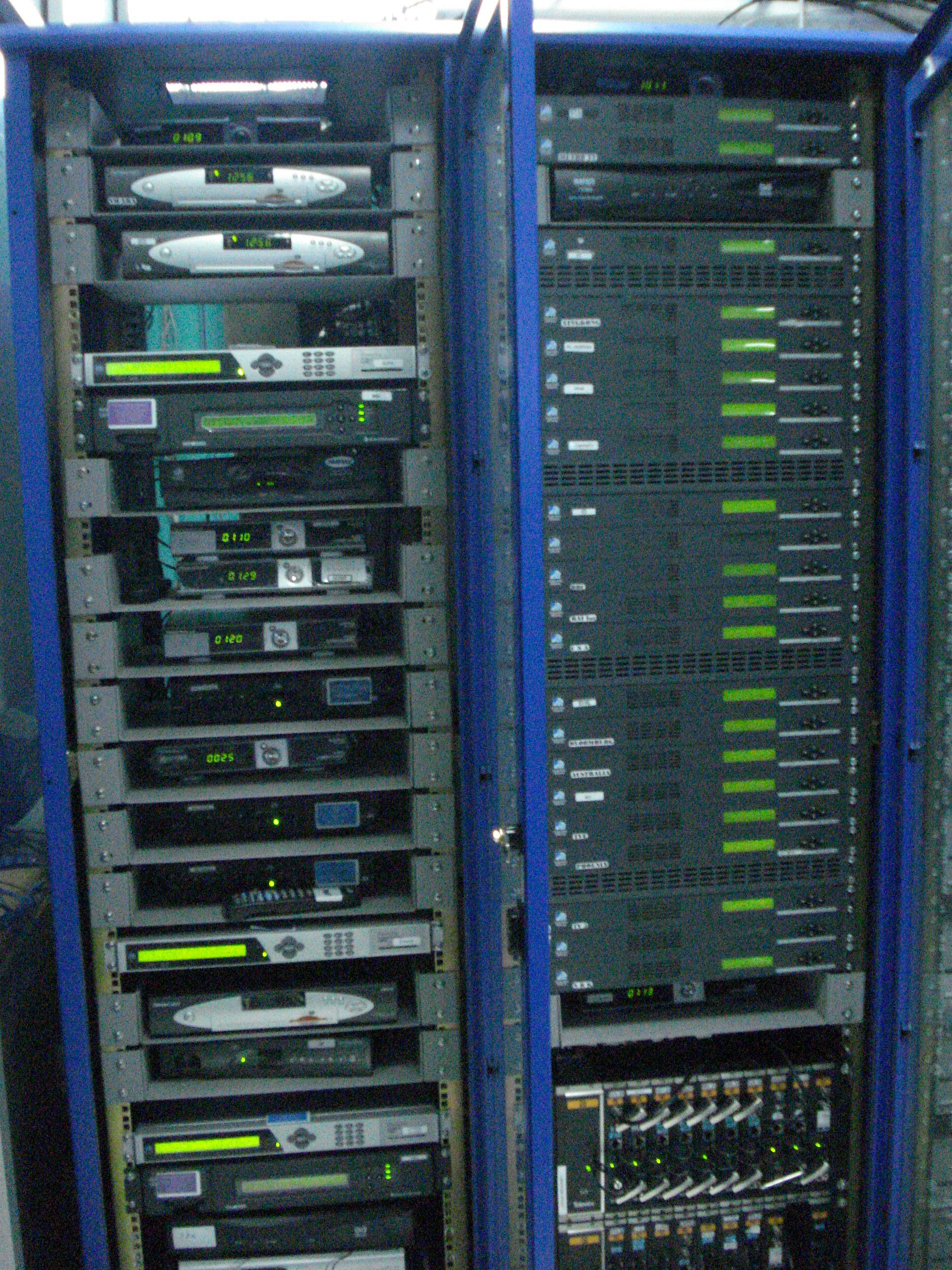
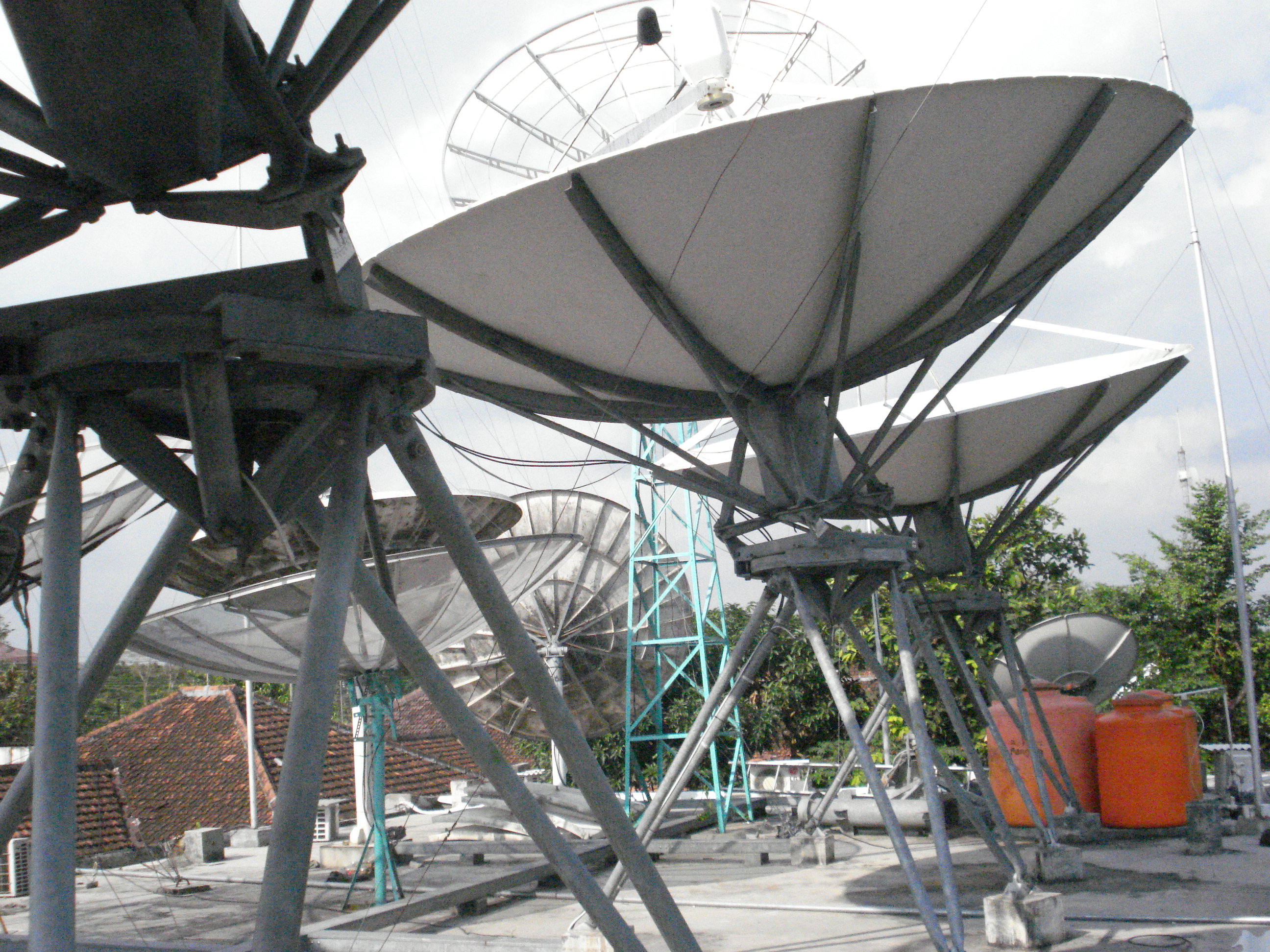
Head end MATV yang baik
Head end, sebagai sentral atau pusat jaringan distribusi gambar (MATV?CATV) agar mendapatkan hasil maximal,tentu juga harus dilakukan hal yang maximal juga.karena bila gambar atau hasil tidak maximal, tentu gambar di client juga jelek/tidak maximal. Ada beberpa hal yang perlu diperhatikan untuk membangun head end yang baik. Berikut saya tuliskan sedikit tentang head end yang baik :
1. Pastikan channel atau siaran yang akan di distribusikan sudah diterima bagus dari satelite/parabola.(tidak pecah2 atau signal hilang2)
2. Bila ada siaran atau gambar yang diambil dari TV Terestial, lebih baik frequensi distribusi ke jaringan kita dirubah dahulu menggunakan transmodulator.
3. Pastikan frequensi tidak saling bertabrakan antara modulator (diberi jarak minimal 1 channel utuk masing2 modulator)
4. Pastikan output rf modulator tidak sama dengan frequensi tv terestial (bila ada didaerah anda)
5. Pastikan keluaran dari combiner, masing masing rf modulator besarnya sama (rata) atau tidak ada yang lebih tinggi dari lainya. kalau terpaksa ada yang lebih besar/tinggi,usahakan tidak terlalu jauh selisihnya.
6. Pastikan input maximal dan input minimal dari booster atau ampli yang akan digunakan di head end. jangan melebihi atau kurang dari spek pabrik (biasanya tertulis di kemasan/manual book)
7. Untuk setting ampli/booster usahakan signal level frequensi yang tinggi lebih besar dari freq rendah, jadi klo digambar,spektrumnya akan semakin naik nilai levelnya.
8. Selalu lakukan balanching signal secara periodik (minim seminggu sekali)
9. Gunakan Conector yang bagus,dan benar dalam pemasangan konektor dan jangan sampai kendor dalam memasang ke perangkat
10. Gunakan kabel yang bagus
untuk belajar MATV silahkan kunjungi : http://www.masterantena.blogspot.com
POLISI TIDUR
Siapa yang tidak kenal yang namanya Polisi Tidur? itu lho Gundukan atau tanggul yang melintang di tengah jalan yang berfungsi untuk membatasi kecepatan laju kendaraan yang lewat. Disebut Polisi Tidur karena fungsinya yang mirip dengan polisi, yaitu sama-sama memberi peringatan di jalanan agar setiap kendaraan yang lewat untuk berhati-hati dan memperlambat lajunya.
Keberadaan Polisi Tidur sebenarnya sangat membantu keamanan berlalu-lintas karena dapat menekan laju kendaraan yang sering kita lihat ugal-ugalan dan dengan seenaknya sendiri kebut-kebutan. Namun permasalahan adalah bagaimana keberadaan Polisi Tidur sekarang sudah melewati batas kewajaran. Banyak Polisi Tidur yang tidak sesuai standar, sehingga bukannya membuat nyaman, malah menuai cercaan para pengguna jalan. Lihat saja, jika terlalu vertical, besar atau kasar akan membuat kendaraan susah melewatinya, jalan menjadi cepat rusak, belum lagi keluhan bagi para ibu hamil yang melintas dan mereka yang sedang sakit.
Fakta yang ada mungkin terjadi dikarenakan masyarakat tidak (atau belum) mengetahui aturan pembuatan polisi tidur yang standar. Berikut saya akan coba ulas yaa…
Pembuatan Polisi Tidur diatur dalam Kepmenhub no. KM3 tahun 1994.
Yang isinya:
1. Polisi Tidur hanya boleh dibangun di tiga tempat, yaitu: Jalan di lingkungan pemukiman, Jalan lokal dengan kelas III C (Kekuatan dibawah 5ton), dan pada jalan yang sedang dilakukan pekerjaan konstruksi.
2. Syarat-syarat pembuatan Polisi Tidur antara lain:
– Dibuat memanjang dan melintang seperti trapezium
– Tinggi maksimum 12 cm
– Bagian pinggir memiliki kelandaian 15 %
– Di cat dengan warna hitam putih dengan komposisi hitam 30 cm, putih 20 cm.
– Meminta ijin ke dnas perhubungan.
Namun dapat dilihat , fakta yang ada sangatlah timpang. Selama ini Polisi Tidur dibuat asal jadi dan sangat tidak memenuhi syarat pembuatan sehingga membuat penguna jalan bukannya senang malah sumpah serapah yang keluar.
Semoga tulisan ini dapat menjadi referensi bagi kalian yang membaca, khususnya yang ingin membuat Polisi Tidur dan bagi pengguna jalan pada umumnya..
kabel utp
|
|||||||||||
|
Tutorial singkat ini cocok sekali buat Anda yang sedang membuat jaringan komputer ‘MURAH’ khususnya yang terdiri lebih dari dua client yang pake hub (jauh lebih murah daripada router ). To the point! Apa sih kabel UTP itu? Kabel UTP itu adalah kabel khusus buat transmisi data. UTP, singkatan dari “Unshielded Twisted Pair”. Disebut unshielded karena kurang tahan terhadap interferensi elektromagnetik. Dan disebut twisted pair karena di dalamnya terdapat pasangan kabel yang disusun spiral alias saling berlilitan. Ada 5 kategori kabel UTP. Dari kategori 1 sampai kategori 5. Untuk jaringan komputer yang terkenal adalah kategori 3 dan kategori 5. Kategori 3 bisa untuk transmisi data sampai 10 mbps, sedang kategori 5 sampai 100 mbps. Kalau hanya buat misalnya jaringan komputer di kantor atau kampus atau warnet, paling hemat ya menggunakan yang kategori 3. Itu sudah lebih dari cukup. Setahu penulis ada banyak merek yang beredar di pasaran, hanya saja yang terkenal bandel dan relatif murah adalah merek Belden – made in USA. Kalau mau yang lebih murah dan penggunaannya banyak, maka beli saja yang satu kotak, panjangnya sekitar 150 meter. Jangan lupa beli konektornya. Konektornya bentuknya seperti colokan telepon hanya saja lebih besar. Bilang saja mau beli konektor RJ-45. Satu lagi yang sangat penting, Anda harus punya tang khusus buat memasang konektor ke kabel UTP, istilah kerennya adalah “crimp tool”. Alat ini gunanya untuk ‘mematikan’ atau ‘menanam’ konektor ke kabel UTP. Jadi sekali sudah di ‘tang’, maka sudah tidak bisa dicopot lagi konektornya. Dan kalau mau yang lebih OK, biar tidak nanggung maka beli pula sebuah LAN tester. Anda bisa membeli yang merek dari Taiwan saja agar lebih murah. Bentuknya seperti kotak dan ada lampu LED-nya delapan pasang dan bisa kedap-kedip. OK sekarang peralatan udah siap, penulis mulai saja. Secara umum, pemasangan kabel UTP tersebut ada dua tipe, yaitu tipe straight dan tipe cross. Disebut tipe straight soalnya masing-masing kabel yang jumlahnya 8 itu berkorespondensi 1-1, langsung. Sedangkan disebut cross soalnya ada persilangan pada susunan kabelnya. Bingung? OK! Untuk tipe straight itu digunakan untuk menyambungkan kabel dari client ke hub. Sedangkan untuk tipe cross adalah untuk client langsung terhubung ke client (cpu to cpu) atau juga dari hub ke hub. Kita bahas dulu yang tipe straight Yang penting adalah pin nomor 1,2,3 dan 6. Jadi misal yang disambung hanya pin 1,2,3 dan 6 sedangkan pin yang lain tidak dipasang, tidak jadi masalah. Untuk lebih jelasnya silakan lihat gambar di bawah yang penulis foto dari sebuah buku. Waktu akan memasangnya, maka potong ujung kabelnya, kemudian susun kabelnya trus diratakan dengan pisau potong yang ada pada crimp tool. Andak tidak perlu repot harus melepaskan isolasi pada bagian ujung kabel, karena waktu Anda memasukan kabel itu ke konektor lalu ditekan (pressed) dengan menggunakan crimp tool, sebenarnya saat itu pin yang ada di konektor menembus sampai ke dalam kabel. Perhatikan, agar penekannya (pressing) yang keras, soalnya kalau tidak keras kadang pin tersebut tidak tembus ke dalam isolasi kabelnya. Kalau sudah kemudian Anda test menggunakan LAN tester. Masukkan ujung ujung kabel ke alatnya, kemudian nyalakan, kalau lampu led yang pada LAN tester menyala semua, dari nomor 1 sampai 8 berarti Anda telah sukses. Kalau ada salah satu yang tidak menyala berarti kemungkinan pada pin nomor tersebut ada masalah. Cara paling mudah yaitu Anda tekan (press) lagi menggunakan tang. Kemungkinan pinnya belum tembus. Kalau sudah Anda tekan tetapi masih tidak nyambung, maka coba periksa korespondensinya antar pin udah 1-1 atau belum. Kalau ternyata sudah benar dan masih gagal, berarti memang Anda belum beruntung. Ulangi lagi sampai berhasil. Berikut adalah gambar dari bawah dari ujung kabel UTP yang sudah dipasangi konektor dan berhasil dengan baik (urutan pewarnaan pinnya ikut standar): Dan kalau yang ini tidak standar, coba perhatikan urutan warna pinnya, sangat tidak standar, tapi tetap saja bisa, yang penting korespondensinya satu satu (khusus tipe straight): Tipe Cross Masih bingung? Begini cara mudahnya: Ujung pertama: 1. oranye muda 2. oranye tua 3. hijau muda 4. biru muda 5. biru tua 6. hijau tua 7. coklat muda 8. coklat tua Maka di ujung yang lain harus dibuat begini: 1. hijau muda 2. hijau tua 3. orange muda 4. biru muda 5. biru tua 6. orange tua 7. coklat muda 8. coklat tua Sudah agak lebih mengerti? Jadi disini posisi nomor 1, 2, 3 dan 6 yang ditukar. Nanti jika dites menggunakan LAN tester, maka nantinya led 1, 2, 3 dan 6 akan saling bertukar. Kalau tipe straight menyalanya urutan, sedangkan tipe cross ada yang lompat-lompat. Tapi yang pasti harus menyalasemua setiap led dari nomor 1 sampai 8. OK, selamat membangun jaringan komputer. Semoga Anda bisa berhasil sewaktu memasang konektor pada kabelnya. Semoga ilmu ini berguna buat Anda, soalnya waktu dulu penulis pertama kali membuat jaringan hasilnya lucu sekali, untuk mengupas kabelnya penulis masih menggunakan cutter, padahal sudah ada fasilitasnya di crimp toolnya. Tambah lagi ujung-ujungnya tiap kabel penulis kelupas lagi menggunakan cutter, padahal yang betul tidak perlu dikupas satu-satu, biarkan saja rata, karena nantinya apabila di ‘crimp tool’ maka pin tersebut masing-masing akan tembus ke dalam kabelnya. Semoga Anda tidak melakukan hal sama seperti penulis dulu. Demikian tulisan mengenai cara membuat sambungan kabel UTP untuk jaringan komputer. Semoga berguna bagi Anda semua. Jika ada komentar atau saran bisa dikirimkan melalui baliwae@baliwae.com. Untuk membaca tulisan menarik lainnya silakan menuju ke situs Sony AK Knowledge Center dengan alamat di www.sony-ak.com. Terima kasih. |
